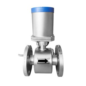
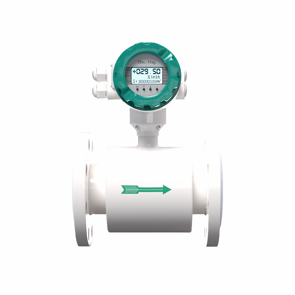
Ultimate Guide to Flange-Mounted Electromagnetic Flowmeter Installation
This guide covers installation standards for vertical and horizontal pipelines, diameter reductions, and special operating conditions.
1. Core Principle: Full Pipe Requirement
The physical basis of electromagnetic flow measurement requires that the measuring tube must be full of fluid at all times.
- Never install in partially filled pipes, pipes with excessive air bubbles, or sections where the liquid might drain out.
2. Installation Orientation & Scenarios
A. Vertical Pipelines
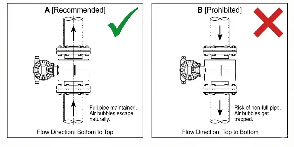
[Recommended]
- Flow Direction: Fluid must flow from bottom to top.
- Reason: This ensures gravity keeps the pipe full and air bubbles naturally rise out, preventing them from getting trapped in the sensor.
[Prohibited]
- Flowing Downwards: Unless you can guarantee backpressure maintains a full pipe at all times (even when pumps stop), downward flow is strictly prohibited.
B. Horizontal Pipelines
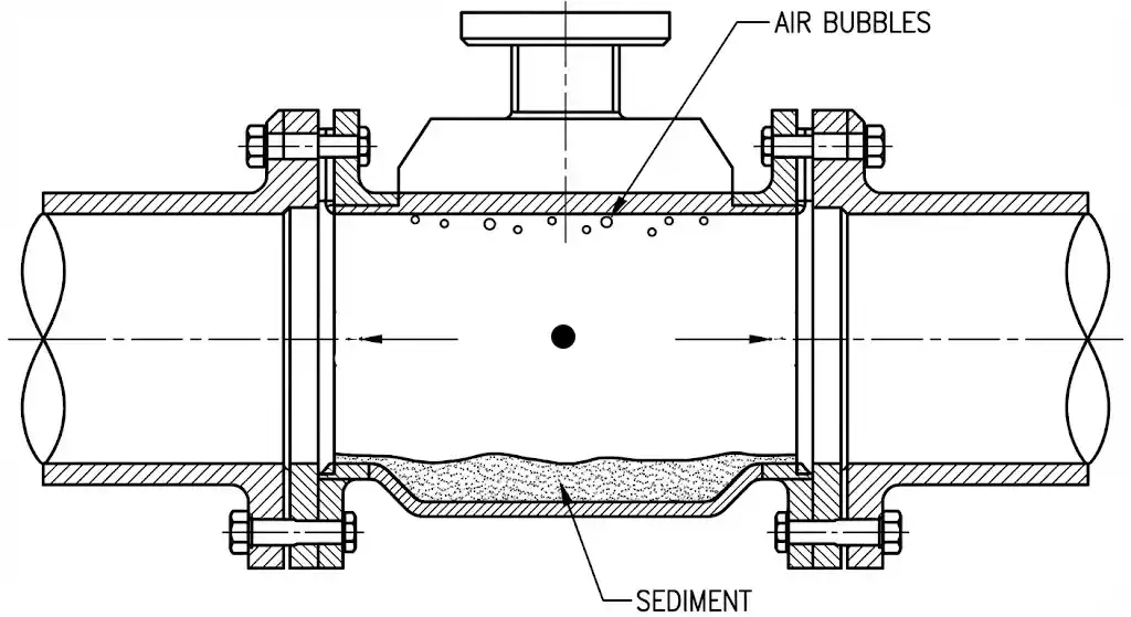
- Electrode Axis: The electrode axis must remain horizontal.
- Reason:
- Top: Prevents air bubbles from gathering at the top electrode, causing insulation and measurement instability.
- Bottom: Prevents sediment from covering the bottom electrode and interfering with the signal.
C. High & Low Points
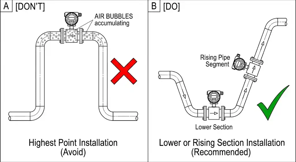
- Don’t: Never install at the highest point of the piping system. This is where air bubbles accumulate.
- Do: Install in lower sections or rising pipe segments.
D. Open Discharge Pipes
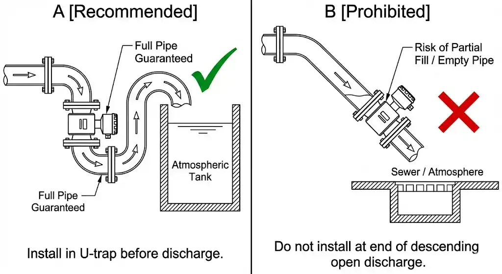
If the pipeline discharges directly into the atmosphere (e.g., sewer or tank):
- The flowmeter should be installed at a low point or within a U-trap (siphon) section before the discharge outlet to ensure the sensor remains full.
- Note: Do not install at the end of a descending pipe leading directly to the atmosphere.
3. Straight Pipe Run Requirements
To eliminate fluid disturbance (turbulence), sufficient straight pipe runs must be maintained before and after the flowmeter. $D$ represents the flowmeter diameter.
| Disturbance Source | Upstream Requirement | Downstream Requirement |
| Elbow / Tee | ≥ 5D (Recommend 10D) | ≥ 3D |
| Fully Open Valve | ≥ 5D | ≥ 2D |
| Control Valve | Never Upstream | ≥ 5D (Valve must be downstream) |
| Pump | Never Upstream | ≥ 3D (Flowmeter must be downstream) |
Critical Note:
- Pumps: The flowmeter must be installed downstream of the pump (high-pressure side). Installing on the suction side (upstream) can cause vacuum, leading to liner collapse or empty pipes.
- Control Valves: Must be installed downstream of the flowmeter. Throttling flow upstream creates severe cavitation and turbulence, destroying measurement accuracy.
4. Installation with Pipe Reducers
When the process pipe diameter differs from the flowmeter diameter (usually Pipe > Meter), concentric reducers are required.
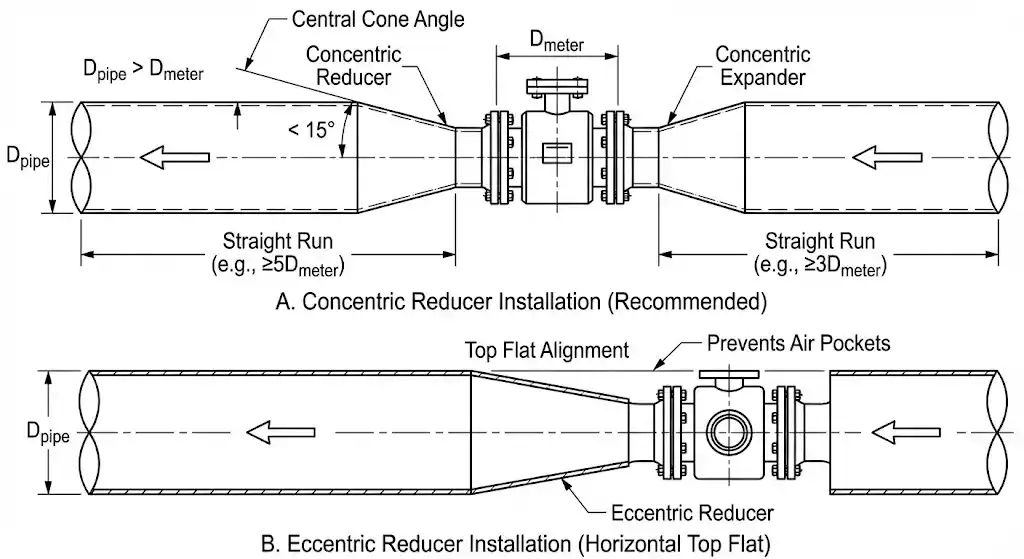
Selection & Installation Rules:
- Central Cone Angle: The central cone angle of the reducer should be less than 15°. Larger angles cause excessive pressure loss.
- Position: Reducers should ideally be outside the straight run calculation, or the straight run length should be measured starting from the reducer.
- Concentric vs. Eccentric: Concentric reducers are recommended. If using eccentric reducers (often used in horizontal pipes to prevent air pockets), ensure the installation is Top Flat.
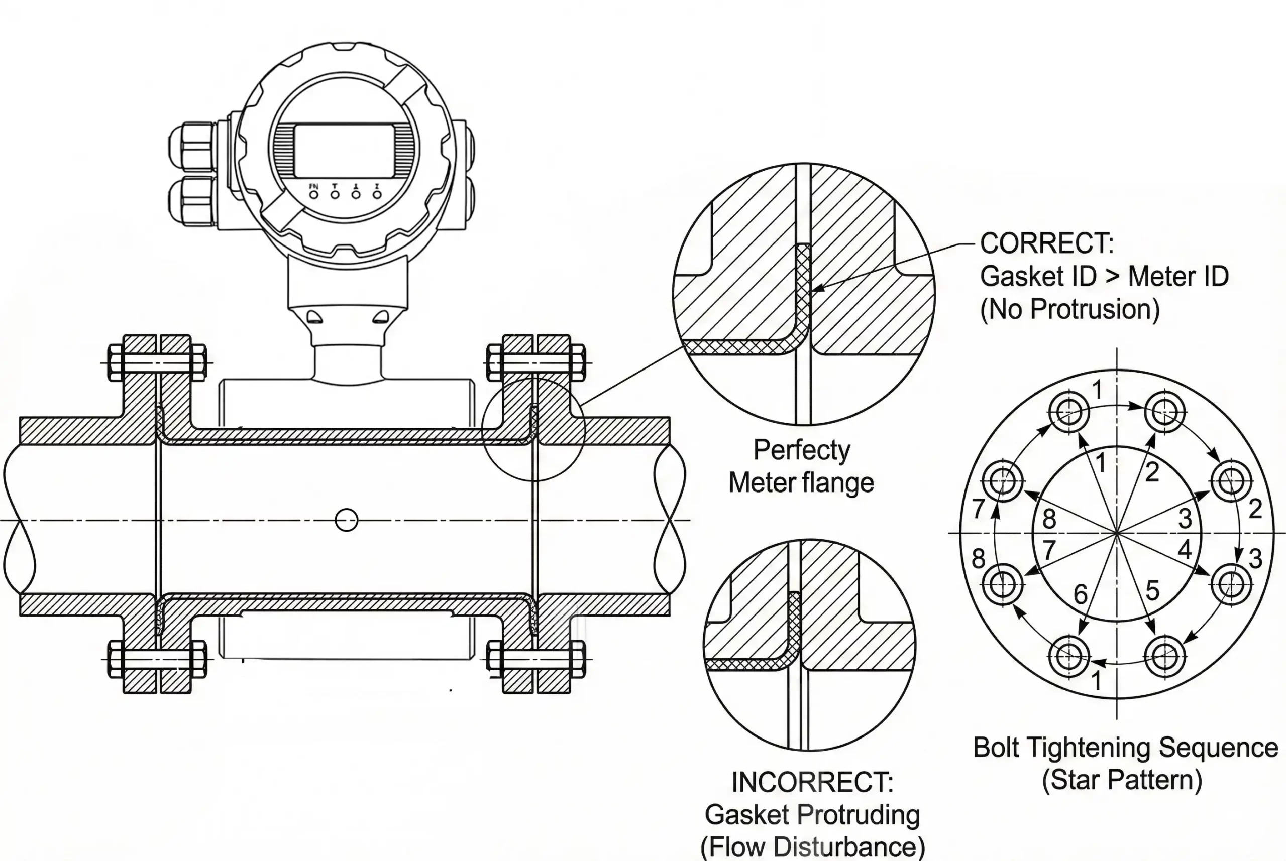
5. Flange Connection & Gaskets
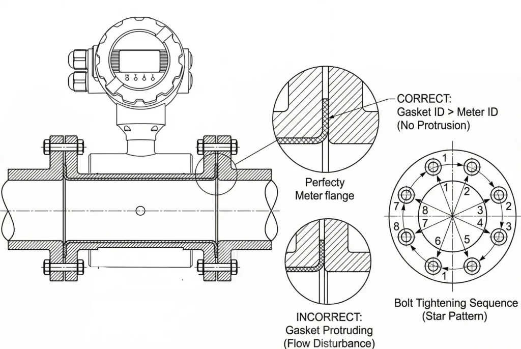
- Parallelism: The flanges on both sides must be parallel. Never use the flowmeter body to forcibly pull together deformed pipes; this will damage the sensor liner.
- Gasket Installation: The gasket inner diameter must be larger than the flowmeter measuring tube inner diameter. Gaskets must never protrude into the pipe, as this alters the flow profile and affects accuracy.
- Bolt Tightening: Bolts must be tightened evenly in a diagonal cross sequence (star pattern).
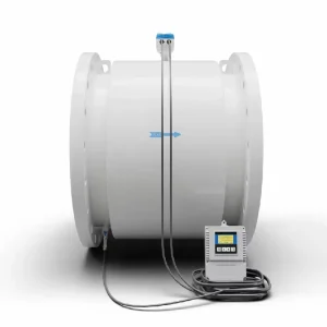
6. Grounding Requirements (Crucial)
Mag meters operate on weak signals; proper grounding is essential to shield against noise.
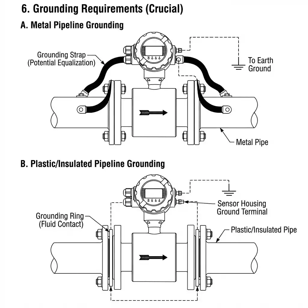
- Metal Pipelines: Use grounding straps to connect the flowmeter housing to the pipe flanges to ensure potential equalization.
- Plastic/Insulated Pipelines: Grounding rings or grounding electrodes must be installed. The fluid must contact the metal grounding ring, which is then connected to the sensor housing ground terminal.
7. Summary Checklist
- Flow Direction: Matches arrow.
- Full Pipe: Position guarantees full pipe.
- Straight Pipe: Upstream 5D, Downstream 3D.
- Valves/Pumps: Pump before, Control Valve after.
- Flanges: Gasket not blocking flow.
- Grounding: Independent grounding resistance < 10Ω.
admin
System Administrator
Thank you for reading our technical insights and industry news.