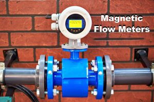
A very popular type of flow meter that is useful in many applications and line sizes is the magnetic flow sensors.
Industrial processes require accurate and repeatable flow measurement, whether it is feed streams, tank recirculation loops, product transfer lines and many others.
Within this article we shall:
–Make you acquainted with the operating principles of a magnetic flow sensor,
Explain the physical features of a magnetic flow sensor that enable it to be of process control value,
18 – Explain how magnetic flow sensors may be implemented in a measurement and control system.
What is a magnetic flow sensor?
Magnetic flow sensors aim at transforming the velocity of a moving fluid into a quantifiable electrical signal which is proportional to the flow rate.
There are no moving parts and no obstructions to the flow path inside the magnetic flowmeter, thus these devices are simple to calibrate and maintain.
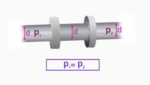
Since magnetic flow meters are often ordered to match in size the upstream and downstream piping, there is essentially no pressure loss through the flow meter, which can be quite beneficial in some flow streams, such as thick slurries.
What are these features and attributes of magnetic flow meters? Let us have a look then. We are going to discuss their operation, when to apply them and what has to be defined in order to pick the right sensor for your job.
Magnetic Flow sensors are commonly referred to as mag meters and we will use this abbreviation to refer to them.
The magic is in the magnet
How a Magnetic Flowmeter physically transforms the velocity into a flow signal which can be utilized within a control system? Let us examine the physical characteristics of how this occurs.
Earlier we stated that mag meters translate a velocity into a recognizable electrical signal. What is the mechanism of this?
Mag meters are usually full-bore sensors, that is, the internal flow path is the same diameter as the upstream and downstream connections.
In this construction there is no limitation of the fluid that can causedistortion of the flow path or may impose a pressure drop.
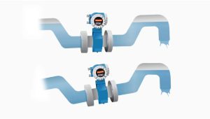
The fluid flows through the mag meter in a straight line through the bore of the sensor. The cylindrical geometry of this regular also permits the constant and directional magnetic field to be created across the flow path diameter.
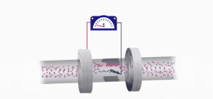
The magic to generate the flow signal lies in the magnet! An iron-core, permanent magnet encloses the mag meter and generates a magnetic field, to be set up, with lines of magnetic flux that vertically penetrates the entire cross-section of the pipe and the fluid that is flowing.
This geometry is quite essential. The moving fluid will flow through these lines of magnetic flux at right angle or perpendicular to the lines of magnetic flux.

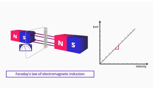
Faraday’s law
Michael Faraday in 1831 noted that a voltage is induced across any conductor when it moves perpendicularly through a magnetic field and that the voltage is proportional to the speed of that conductor. This is referred to as Faraday -s Law of Electromagnetic Induction.
In order to induce a voltage by Faraday law, we require a conducting movement.
What is the conduit in our flow app?
We had said that our mag meter contains a stationary, permanent magnet, and hence the flowing fluid must be the conductor! And it is, too!
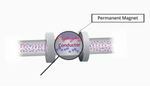
And as the fluid that flows through the magnetic field does so at right angles, then by the Law of Faraday a voltage should be induced that is proportional to the velocity of the fluid.
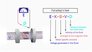
Faraday’s Law can be expressed simply as E is proportional to k × B × V × D, where:
– E is The voltage generated in the fluid,
– k is The meter-specific constant,
– B is The strength of the magnetic field,
– V is The velocity of the fluid,
– D is The distance between the mag meter’s electrodes.
Signal transmission
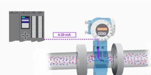
This created EMF, or electrical potential, or voltage is detected by two leads, or electrodes, attached to the transmitter on the mag meter.
The transmitter takes the strength of this electrical signal and converts it into volumetric flow rate and establishes the 4 to 20 milliamp output of the transmitter to indicate an analog signal to the control system
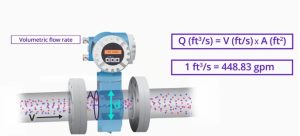
The transmitter gives out a volumetric flow rate. The velocity of the flow is measured by the meter.
The diameter of the cross-section and therefore the cross-sectional area is constant and therefore the velocity in feet per second that comes out of the measurement times the constant area in square feet, will give a volumetric flow rate ate of cubic feet per second.
This measure may be rescaled to any unit of volumetric flow rate including gallons per minute.
Conductive fluids
However, we cannot ignore one important parameter that we have earlier mentioned. We need to have a moving conductor in order to induce the needed electrical signal.
We stated that the conducting fluid was the one that flows, hence the fluid to be used must be conductive in order to use a magnetic flowmeter.
What is the significance of a conductive fluid? This is to say that the fluid should have the capacity to transmit an electrical charge thus creating a voltage to be detected by the electrodes of the mag meter.
Distilled water however is very low in conductivity, and is not measurable on a mag meter.
The vegetable and other oils, hydrocarbons and most organic solutions cannot be metered using a mag meter.
Magnetic flowmeters can easily measure in addition to seawater, wastewater flows and ionic solutions like acids.
To be confident of good flow readings with a mag meter, fluids need to possess a conductivity higher than 10 micro-Siemens-per-centimeter.
Other considerations for installation
Besides their ability to measure a great variety of fluids, in-line magnetic flowmeters can be lined with Teflon or other liners to cope with corrosive or erosive fluids, such as slurries and acids.
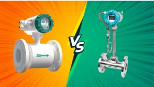
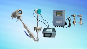
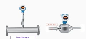
Types of magnetic flowmeters
There are other types of magnetic flowmeters that can be used, including insertion type, typically used with larger pipe sizes, and low-flow magnetic flowmeters, which are typically ⅛ inch to ½ inch in diameter.
Magnetic flow meter grounding
When installing a magnetic flow meter in process piping, it is vitally important to follow the manufacturer’s recommendation for grounding.
The electrical signal produced in a mag meter is a very small DC voltage, and stray voltages along a pipe due to welding equipment or other large electrical loads in the plant.
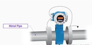
For conductive metal pipes, the outside flanges and transmitter casing should be bonded and grounded.
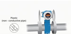
For plastic or other non-conductive piping, manufacturer-recommended grounding rings should be installed to prevent stray voltages.
Grounding rings are also recommended for fluids with low conductivity, less than 100 micro-Siemens-per-centimeter.
Magnetic flow meter Transmitter
Transmitters are always used with mag meters. They convert the small DC voltages generated by the flowing fluid into signals that can be connected to the control system.
The following transmitter outputs are available:
– 4 to 20 milliamps
– Profibus PA
– Foundation Fieldbus
– IO-Link
Magnetic flow meter specification
Besides the conductivity of the fluid and the necessity of grounding rings, there are some other crucial points that have to be taken into account when magnetic flowmeters are specified.
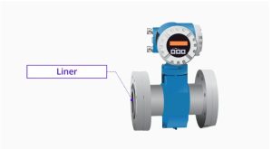
When the fluid is either corrosive or abrasive, then a compatible liner is to be specified. It is also possible to replace these liners in case they are worn out and they do not interfere with the accuracy of the measurements.
Summary
In this paper we have familiarized you with the operating principle of the magnetic flow sensor, its physical characteristic and the application of mag meters in industrial measurement and control systems.
We were able to show the linearity between velocity of the flowing fluid and the electrical signal developed according to Faraday Law.
Proper grounding, choosing the most suitable place to make the installation, and knowledge about the minimum and maximum limits of the flow in which the meter can measure the flow accurately will facilitate this.
Then the next time you look at a magnetic flow meter installed in a plant you will be much more knowledgeable about how this elegant, yet uncomplicated sensor can measure flow.
We are a manufacturer of automatic flow meters with many years of experience in the industry. We have strong independent research and development capabilities and are a leader in the flow meter industry. Our main products include electromagnetic flow meters, vortex flow meters, turbine flow meters, ultrasonic flow meters, Coriolis flow meters, various solenoid valves, level meters, control units and valves, etc. Welcome to purchase –Best Instrument