 Electromagnetic flowmeter are installed throughout the water supply system in most irrigation applications. In farm irrigation systems the meter is usually applied in the control or billing applications.Since the design of a flow meter is such that entrapped air could lead to numerous stability and reading errors, it could interfere with the overall performance of the flow meter system. Through designing the system keeping in view this issue we can avoid this problem to a greater functioning and optimization.
The problem
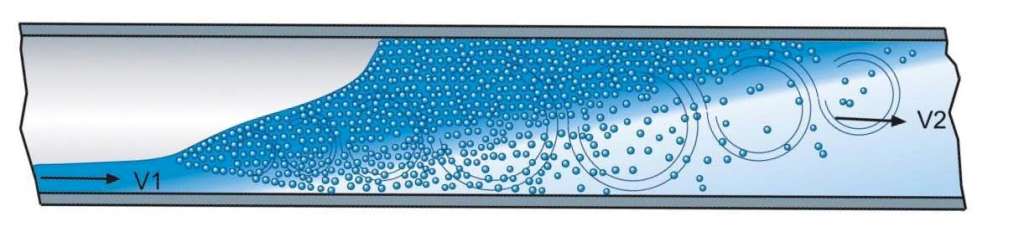
A magnetic flow meter, creates a magnetic field within the flow tube (sensor).The conduction of a conductive liquid through the magnetic field according to Faraday induces a voltage signal which is detected by electrodes placed on the walls of the flow tube.Entrapped air may give a erratic reading and /or a highly inaccurate reading with possible over reading. The instability of the reading may cause many meters to enter a fault mode.Most manufacturers will give comprehensive installation guidance on how their meters should be installed but seldom will they talk about how the air flows in the pipeline, and what are the best methods of reducing these issues.How to move the entrapped air away from the flow meter
The assumptions made will generally be that air in a pipeline will at all times settle at the top of the pipe, and will be displaced when flow is conveyed through a horizontal pipeline.But this is not a constant assumption. In many cases a certain minimum velocity of water is needed to entrain the air in a pipeline and the larger the pipe diameter, the higher the air velocity which must be used.Most Magflow installations are scaled to the pip diameter (and not the flow in the pipe). This implies that the velocity of water can be significantly low as 0.5 m/s which when entrapped air is present, can be quite problematic.To move air in a pipe, the following are the particular water velocities that will be needed based on the example of a flat pipe, zero gradient:- DN50? 0.4 m/s
- DN150? 0.7 m/s?
- DN300? 1 m/s?
- DN600? 1.5 m/s?

What this example illustrates, is that the larger the diameter of the pipes the higher the needed velocity will be. In the absence of this velocity the air pocket will simply stay put.
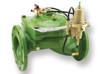
One should also comprehend the impact of the water pressure on the character of the air within the pipeline. The less the pressure the more the entrapped air.This can further add to the effect on the performance of the flow meter. The trapped air is less damaging with the rise of pressure in the pipeline. It can be done by fitting pressure sustaining valves in the network to maintain a constant pressure in the system.The installation of the meter with a rising gradient is one of the solutions as it will guarantee that the air will be directed to a higher location. Appropriate air release valves may be fitted so that air may be released in the pipe and the flow capability of the system utilised fully.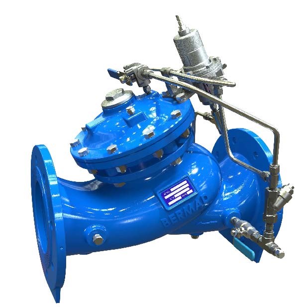
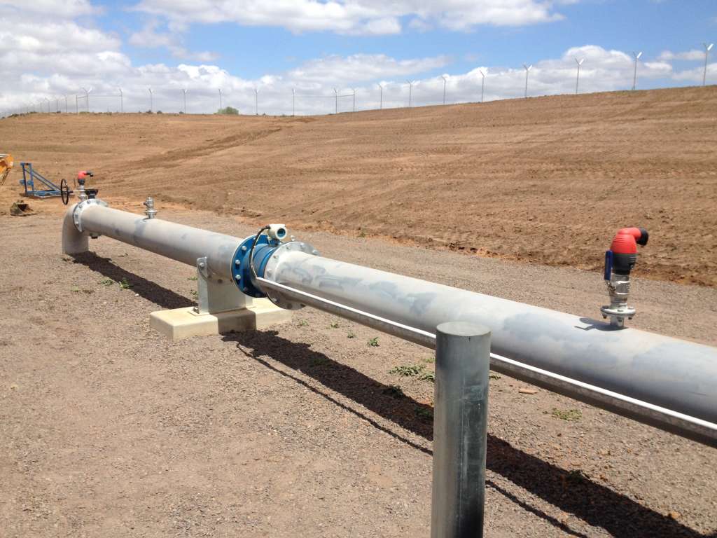
 The meter can be installed at a rising gradient so that the air will go to a high place, which is one of the solutions. Appropriate air release valves may be fitted so that air in the pipe may be released and the flow capacity of the system utilised to its fullest capacity.
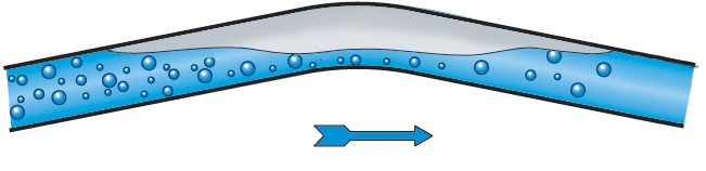
We would recommend that the least slope in an upward flow need to have a gradient of 1 : 500 or more so as to cause the air pocket to climb out of the meter.
Meter with a slight rising gradient with air release at the top.
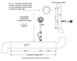
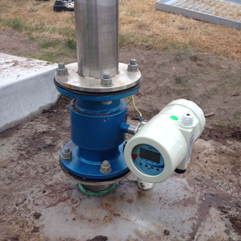
The second remedy would be to install meter in a vertical position with flow directed upwards. This will make sure that the air will always rush past the meter at high speed without creating constant troubles.
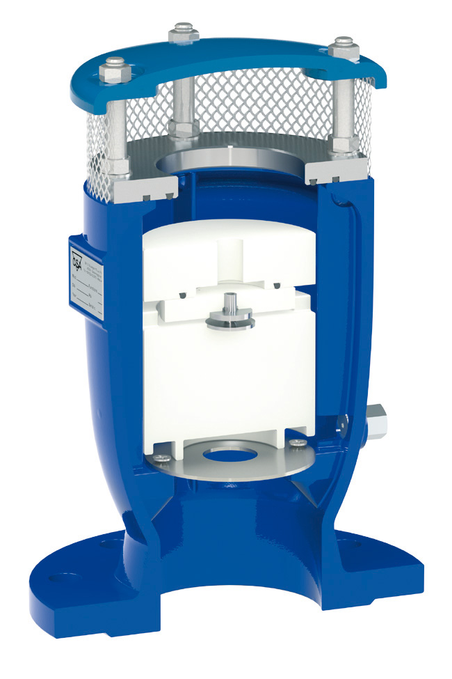
 One of the common rules of any installation is that the meter should always be filled with water. This cannot always be done, because some of the network might drain out when pumps are switched off.Then it is essential to make sure that the design has appropriate air release valves to get rid of the air when the pump is started–so that the meter will start recording as soon as the flow has gone by.The air valve design is also important so that the trapped air can be released. Kinetic air valves or vacuum breakers Kinetic air valves or vacuum breakers should not be used, combination air valves with an automatic and kinetic orifice are good practice in these types of applications.These combination valves will make sure that more amounts of trapped air are discharged easily during the filling and the pipeline operation.
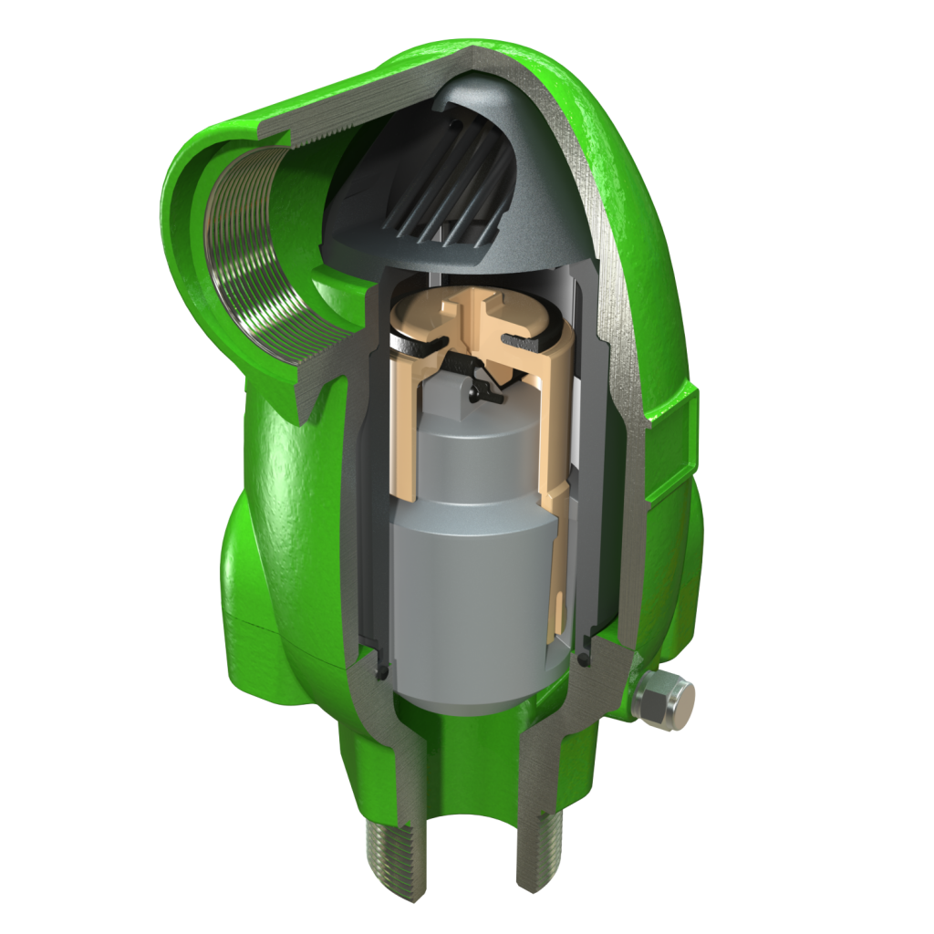
We are a manufacturer of automatic flow meters with many years of experience in the industry. We have strong independent research and development capabilities and are a leader in the flow meter industry.
Our main products include electromagnetic flow meters, vortex flow meters, turbine flow meters, ultrasonic flow meters, Coriolis flow meters, various solenoid valves, level meters, control units and valves, etc.
Welcome to purchase –Best Instrument