
What is an Electromagnetic Flow Meter?
First let¡¯s examine how an electromagnetic flow meter functions. Coils on the sensor produce a magnetic field. When a conductive fluid moves through the magnetic field, its charged particles are dispersed, generating an induced voltage. Within the sensor, two electrodes detect the induced voltage generated by the moving ions and subsequently the transmitter translates that readout into a flow rate. Measurement can be made in a way that leaves the pipe unaltered and produces no pressure loss.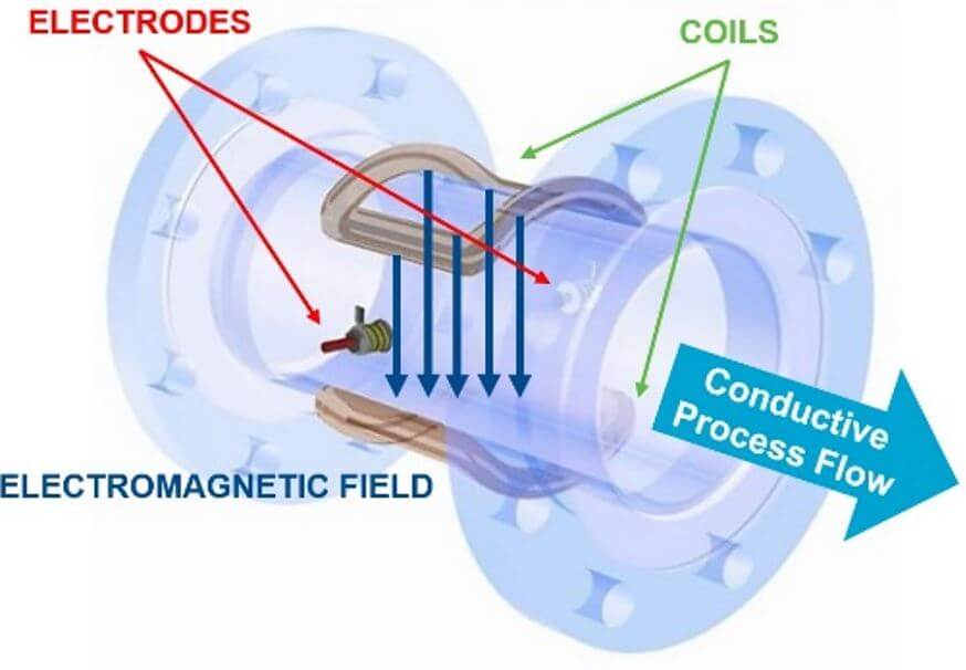
Reasons for Installation Requirements.
According to the manufacturer, a magnetic flow meter installation requires straight sections of pipe extending upstream and downstream. In keeping with industry practice, the upstream straight run should extend five times the pipe diameter from the inlet and the downstream straight run should be twice the diameter from the outlet, as illustrated below in the figure.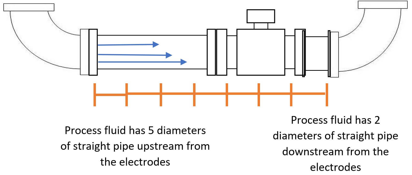 In moving through a straight pipe, a conductive incompressible fluid acquires a more uniform flow profile and steady velocity, causing the most precise assessment of its flow rate. In a short-run configuration, an upstream disturbance disturbs the smooth flow profile and induces fluctuation in the fluid velocity as it passes over the meter. Such variation introduces an offset in the flow measurement accuracy, yet the meter will still yield a measure that is both consistent and reproducible. A further discussion concerning the origin of this shift in accuracy in a short-run installation is presented in the section that follows.
Effects on Accuracy.
Following a blockage, the accuracy of an electromagnetic flow meter shifts owing to an alteration in the fluid flow profile. Upstream disturbance, for example a close-coupled elbow, causes the fluid to swirl, which consequently produces an asymmetric flow profile. Consequently, the induced voltage produced while the fluid passes through the magnetic field differs by a small measure from the value that would be produced under ideal conditions. The illustration below demonstrates the swirling and asymmetry of a fluid following an elbow.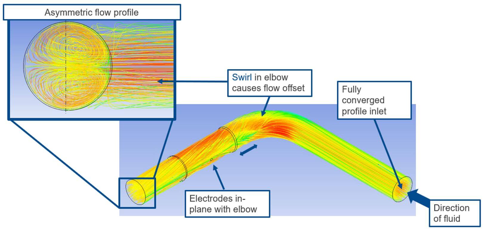 Installation with a five-pipe diameter ahead and a two-pipe diameter downstream monitors a fluid that returns to a more symmetric flow profile, enabling users to confidently rely on the flow meter¡¯s readings accurately reflecting what takes place in their facilities. Even when installing the meter in suboptimal conditions, it will still furnish accurate and consistent flows. Depending on the user¡¯s requirements, a reliable output with modest reduced accuracy satisfies the application¡¯s demands. In such cases, achieving higher accuracy nonetheless requires measures such as extra electrodes, refinements to the sensor configuration, or adjusted installation requirements.
Types of Zero Diameter (0D) installations.
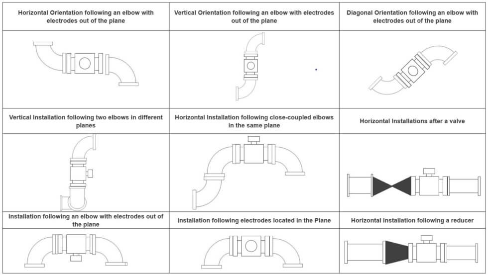
Manufacturers supply dedicated installation guidelines to correspond to the stated accuracy of the electromagnetic flow meter. Nonetheless, it is virtually impossible to account for every imaginable installation scenario. Installation of a meter beyond the specified configuration for accuracy increases the likelihood of performance that does not meet expectations. Needed considerations encompass:- Sensor Direction: Horizontal, vertical or diagonal
- Obstacles:?Close-coupled valves, elbows, T-fittings, build-up in the pipe, insertion devices, and nominal diameter differences
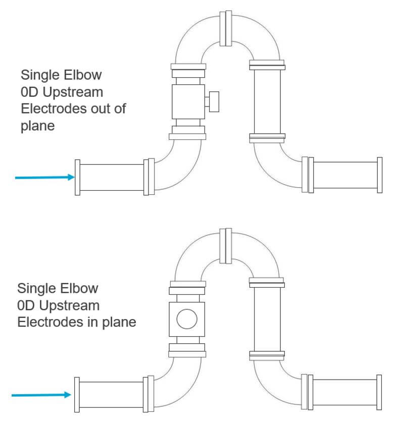
- Electrode Orientation:?In the plane or out of the plane
Installation Accuracy.
Increased insight into the effects of flow profiles and disturbances on magnetic flow meter accuracy enables users to make more informed decisions concerning their individual installations. In practice, the circumstances rarely permit the ideal arrangement of five pipe diameters upstream of the inlet and two downstream of the outlet.There exist exceptions where particular installations provide higher accuracy than those listed above with a zero-diameter (0D) configuration. For instance, a zero-diameter installation with electrodes positioned perpendicular to the plane of an individual upstream elbow leads to a quarter-percent shift yielding the results shown below:*With high accuracy calibration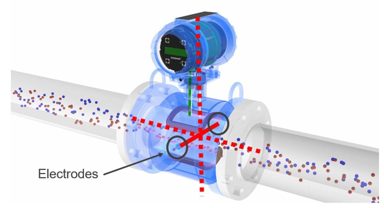
To Sum it up.?
To sum up, electromagnetic flow meters perform optimally when installed with straight inlet and outlet runs of 5 and 2 diameters each. Nonetheless, in a lot of installations, particularly for larger diameters, the cost of securing these lengthy straight runs can be prohibitive, making the practice practically untenable. Consequently, installations generally exhibit close-coupled elbows and assorted upstream disturbances. Even though the magnetic flow meter¡¯s repeatability remained exceptionally high, its absolute accuracy was still called into question. Emerson has undertaken extensive testing and empirical evaluations to gauge the effect that short-run installations have on our Rosemount magnetic flow meter products. Consequently, this evidence empowers users to adopt this technology with confidence in all their applications, despite installation limitations.We are a manufacturer of automatic flow meters with many years of experience in the industry. We have strong independent research and development capabilities and are a leader in the flow meter industry. Our main products include electromagnetic flow meters, vortex flow meters, turbine flow meters, ultrasonic flow meters, Coriolis flow meters, various solenoid valves, level meters, control units and valves, etc. Welcome to purchase –Best Instrument