Vortex Flow meter Principle and structure
LUGB series vortex flowmeter is a flow meter that uses piezoelectric crystal as a detection element and outputs a standard signal proportional to the flow rate. The meter can be directly matched with the DDZ-Ⅲ instrument system, or it can be used with a computer and a distributed control system to measure the flow parameters of different media. The meter is based on the detection principle of fluid vortex street. The piezoelectric crystal for detecting vortex street does not contact the medium. The meter has the characteristics of simple structure, good versatility and high stability.
Vortex Flow meter Product Features
1. High temperature resistance: The sensor measuring probe is encapsulated with a special process, and the high temperature resistance can reach 350℃
2. Strong versatility: Strong versatility, can measure unclean gases and liquids
3. Long service life: The sensitive element is sealed in the probe body, the detection element does not contact the measurement medium, and the service life is long
4. Compensation design: The sensor adopts compensation design to improve the seismic resistance of the instrument
5. Simple structure: Simple structure, no moving parts, high durability
6. Not affected by the medium: Within the specified Reynolds number range, the measurement is not affected by the temperature, pressure, and viscosity of the medium
7. Good safety: The flow meter can be used in explosion-proof occasions, with good safety
8. Wide range ratio: Wide range ratio, up to 10:1, 15:1
Vortex Flow meter Technical parameters
| Ambient temperature |
(-40~55)℃ |
| Relative humidity |
(5~90)% |
| Atmospheric pressure |
(86—106)Kpa |
| Nominal diameter |
(15~1500)mm (insertion structure for greater than 200mm) |
| Measuring medium |
Liquid, gas, steam |
| Nominal pressure |
1.6Mpa 2.5Mpa 4.0Mpa |
| Medium temperature |
(-40~+350)℃ |
| Verification interval |
years – 4’ |
| Accuracy |
0.5%FS, 1.0%FS, 1.5%FS, 2.5%FS |
| Linearity |
≤±1.5% |
| Repeatability |
≤0.5%, ≤1.0% |
| Output signal |
Voltage pulse |
| (4~20)mA DC (two-wire) |
| Power supply |
Voltage pulse 12V DC or 24V DC |
| Current type 24V DC |
| Intelligent current type 24V DC |
| Intelligent battery type 3.6V DC |
| Load resistance |
Upper limit load resistance does not exceed 350Ω |
| Body material |
304 stainless steel |
| Connection method |
(15~300)mm Flange card-mounted structure |
| (200~1500)mm Plug-in structure |
| Protection level |
IP65, IP67 |
| Cable interface |
PG10 |
| Explosion-proof type |
Intrinsically safe type; Flameproof type |
| Explosion-proof mark |
iaⅡCT6; dIIBT4 |
Vortex Flow meter Structural dimensions
| Nominal diameter |
Inner diameter |
Snap-on body |
| Length L |
Outer diameter D |
Overall height H |
| 15 |
15 |
50 |
88 |
335 |
| 20 |
20 |
50 |
88 |
335 |
| 25 |
25 |
50 |
88 |
335 |
| 32 |
32 |
50 |
88 |
335 |
| 40 |
39 |
50 |
88 |
335 |
| 50 |
49 |
70 |
88 |
335 |
| 65 |
64 |
70 |
105 |
345 |
| 80 |
79 |
80 |
117 |
365 |
| 100 |
99 |
80 |
140 |
382 |
| 125 |
125 |
70 |
168 |
395 |
| 150 |
149 |
70 |
190 |
425 |
| 200 |
207 |
|
|
|
| 250 |
259 |
|
|
|
| 300 |
309 |
|
|
|
| Execution |
compact |
| Nominal flange diameter |
DN, MM – 80; |
| Nominal pressure at flange |
PN, bar – 40; |
| Nominal diameter of the sensor |
DN, MM – 80; |
| Temperature sensor |
built-in (without external cable connection); |
| Pressure sensor |
built-in (without external cable connection) 10 bar; |
| Pressure sensor seal material |
FPM (withstands temperatures ranging from – 40 to + 240°C); |
| Explosion protection |
1Ex db ia IIC T6..T2 Gb X; |
| Primary converter material and process connections |
Stainless steel 316L; |
| Sensor material |
Stainless steel 316L; |
| Converter body material |
cast aluminum with two-layer coating (epoxy resin/polyester); |
| Display |
LCD, with remote control; |
| Menu language |
Russian |
| Program version |
built-in – in compensation of gas consumption based on temperature and pressure; |
| Cable entry |
1 x M20 x 1.5 (stainless steel); |
| Output signal with data transmission |
4…20 mA + HART, pulse (frequency); |
| Output parameters – volumetric flow rate, volumetric flow rate reduced to normal conditions, temperature (built-in sensor), pressure (built-in sensor), vortex frequency, flow velocity, Reynolds number |
|
| Calibration, not less than |
by 3 points; |
| Counter flanges (collar), pcs. |
2 |
| Material |
steel C22; |
| Diameter |
DN, MM – 80; |
| Pressure |
PN, bar – 40; |
| Flange shape |
type B1, EN 1092-1; |
| Welded edge |
standard; |
| Fastener kit and gasket |
There is, |
Characteristics of the measured environment:
| Wednesday |
Associated petroleum gas |
| Density, kg/m3 (at 20 degrees) |
0.7164 |
| Viscosity, mPa·s |
0.0108 |
| Operating flow, m3/h |
0~500 – 1600 |
| Working pressure of the medium, kgf/cm2 excess |
0~2 – 10 |
| Temperature of the measured environment, °C |
0 – 20 – 50 |
Flow meter requirement:
| Property |
Specification |
| Protection class not less than |
IP66; |
| Supply voltage |
12…30 V DC; |
| Limit of permissible relative error of volumetric flow measurement depending on the Reynolds number (Re): |
- for liquid – ±0.75%;
- for gas/steam – ±1.0% (at Re ≥ 20000), – ±2.0% (at 10000 ≤ Re < 20000);
- for gas/steam, with temperature and pressure compensation (reduced to normal conditions) – ±1.5% (at Re ≥ 20000); – ±2.5% (at 10000 ≤ Re < 20000);
|
| Repeatability of measurements |
±0.1% of the measured value; |
| Limits of permissible absolute error of temperature measurements, °C |
±0.5; |
| Limits of permissible reduced error of pressure measurements (from the measurement range, when using a built-in pressure sensor),% |
±0.5; |
| Temperature of the measured environment, °C |
from minus 40…to plus 240; |
| Viscosity of the measured medium, Pa·s |
<= 10; |
| Ambient temperature, °C |
from minus 40…to plus 65; |
| Inter-verification interval, year |
4; |
| Mounting length, mm |
200; |
| Height (from the center of the flange axis), mm |
380.3; |
| Weight, not more than, kg |
19.4. |
Delivery set:
| Flow meter (compact version), pcs. |
1 |
|
| Counter flanges, gaskets and fasteners, complete. |
2 |
|
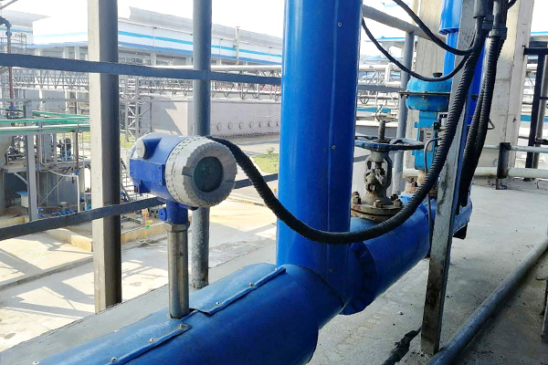
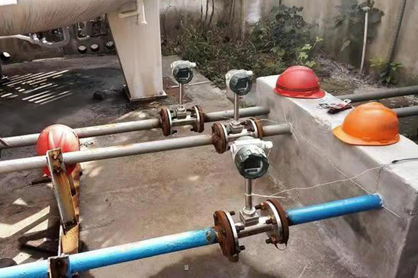
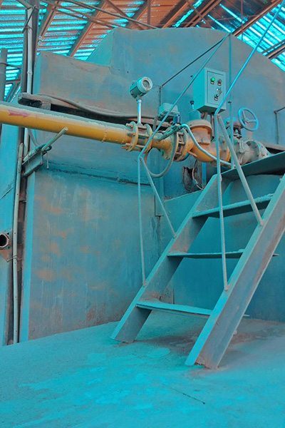
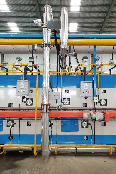
Vortex Flow meter Installation structure diagram

Vortex Flow meter Installation structure diagram of insertion flow meter

Flange card-mounted flowmeter installation structure diagram