Vortex-Shedding History
Theodor von Karman, while fishing in the mountain streams of the Transylvanian Alps, saw that, if you put a bluff body in the flow of a fast river, the fluid will first separate from both sides of the body and, as the boundary layer is detached and curls up, it creates eddies (vortices). The gap between the vortices turned out to be constant, and it only depended on the size of the rock that made them.At the part of the bluff body making the vortex, there is a higher velocity of the fluid and a lower pressure. As it makes its way downstream, the vortex gets more powerful and bigger, until it finally falls apart and detaches. The subsequent stage happens with the formation of a vortex across the back of the bluff shape (Figure 1). The vortices move in turns and each is at the same distance from the next one. When a flagpole stands in the wind (as a bluff body), it sheds wind in vortex rings; this is the reason for the flags rippling back and forth. Vortices are released from the sides of bridge piers, supports for offshore drilling platforms, and tall buildings as well. When designing, engineers should account for the impacts of the vortex-shedding phenomenon. With a closed system, after several pipe diameters downstream of the obstacle, the vortex impact is not harmful.
The design of Vortex Flow Meters
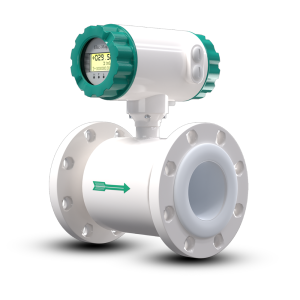
The parts of a vortex flow meter are usually 316 stainless steel or Hastelloy, a bluff body, a vortex sensor assembly, and the electronic transmitter. The electronic transmitter might, however, be placed apart from the other components (Figure 2). Most of these are available in sizes such as ? in. all the way up to 12 in. Vortex meters are as cost-effective as orifice meters in sizes that are smaller than six inches. Body meters without flanges are not expensive, so they are used in most places, but flanged meters are chosen if the process fluid is not safe or is extremely hot.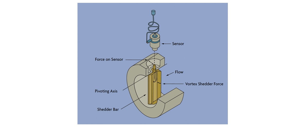
People have adjusted square, rectangular, t-shaped, and trapezoidal bluff body shapes to reach the desired performances. Further studies have demonstrated that only a little changes in linearity, Reynolds number boundary, and sensitivity to distorted velocity profiles occur when you change the shape of a bluff body. The width of the bluff body should be big enough relative to the pipe diameter so that all the flow is involved in the shear. Moreover, having protruding edges on the front part of the bluff body can solve the separation of flow lines regardless of the flow speed. Also, the bluff body length along the flow must meet a given rule compared to its width.
Nowadays, most vortex meters are fitted with piezoelectric or capacitance sensors to detect changes in pressure around the bluff body. These detectors react to the fluctuations in pressure by sending a signal of the same frequency and low voltage. They are modular, inexpensive, can be replaced at any time, and they can be used at any temperature from freezing liquids to boiling steam. Sensors might be inside the meter in one design, and in other designs they are located outside. Sensors equipped in an open way are pressed by vortex pressure and protected in hardened casings to prevent corrosion and wear.
Usually, external sensors in the form of piezoelectric strain gages detect by measuring the forces imposed on the shedder bar by the vortex shedding. Technicians often select external sensors when they face erosive/corrosive materials since this reduces maintenance work, and they use internal sensors when the flow needs to be sensed over a wide range. They are also not as affected by vibrations that come from the pipe movement. The electronics housing is usually safe in explosive and weather conditions, and keeps the electronic transmitter module, as well as the termination points, and optionally devices for measuring and displaying flow rate.The many vortex flow meter designs.
The digital signal coming from a smart vortex meter gives out more than just the flow rate. The flowmeter will correct itself automatically for a lack of straight pipe, misalignment between the bore and mating pipe, bluff body expansion, and a decreasing K-factor as the Reynolds number goes down below 10,000.
They are designed to notify when a component fails using correctly built-in subroutines. Smart transmitters allow you to arrange tests to spot errors in the meter as well as in the application. Likewise, using on-demand testing offers additional help in obtaining ISO 9000 verification.
A certain type of vortex flowmeter is able to measure mass flow. A certain type of design measures the frequency and the strength of vortices taking place at each pulse. It is possible to figure out the density of the fluid and the mass flow in the process using these reading, with an error of only 2% in the span.
the design comes with additional sensors that can spot the vortex frequency, as well as the temperature and pressure of the fluid within the system. From the gathered data, it works out both the density and the mass flow rate. The meter gives a 1.25% of accuracy when monitoring liquid flows and a 2% of accuracy for gases and steam flows. If the process pressure and temperature are needed for additional reasons, having this meter installed is a pleasant and more economical choice compared to adding separate transmitters.
Both accuracy and the range are very important.
Since Reynolds number decreases as viscosity gets higher, the vortex flowmeter¡¯s ability to measure different flows is reduced. Maximum viscosity among these devices is between 8 and 30 centipoises for the given accuracy and rangeability. When the vortex meter is correctly chosen for an application, its rangeability for gases and steam will be better than 20:1, and 10:1 for low-viscosity liquids.
The margin of error for most vortex meters does not go over 1% of the rate for Reynolds numbers greater than 30,000. When Reynolds number reduces, there are greater issues with mistuning the instrument.
When the Reynolds number is lower than 10,000, the error in results may be as high as 10%. Most flowmeters offer some sign when flow is very little, but vortex meters efficiently cut-off at no flow. The signal from the depth meter is also limited below this value, to always be zero or 4 mA (depending on whether the transmitter is digital or analog).
When the Reynolds number does not go above 10,000, this cut-off is reached. If your required minimum flow is at least twice larger than the cut-off, there are unlikely to be any difficulties. In those same situations, a low flowrate may cause issues, as not all details are easy to see.
How Technology Can Be Used and Limitations
It is not usual to recommend vortex meters for batching or intermittent flow situations. This happens since the setting of the batching station dribble flow can be low and beneath the lowest Reynolds number allowed on the meter.
If the data used is very limited, the chance of error is greater. If low-pressure gases are used and the speed of the liquid is not high, their pulses are not strong enough. Hence, the meter service is not reliable and will not be able to measure anything below a threshold of flow. It is still possible to measure with a vortex flowmeter if the reduced range is okay and its size matches the typical flow.
When the process fluid deposits on the bluff body as in sludge or slurry service, the meter¡¯s K factor will change over time. You should avoidusing vortex-shedding flowmeters for these situations. Still, if a single fluid contains just moderate levels of non-coating solids, the application is probably suitable. It was shown during a 2-year study conducted with limestone slurry. After the testing, the K factor only changed by 0.3% from what it was in the factory calibration, although the bluff body and flow tube were left badly damaged.
The meter cannot tell apart the phases in multi-phase flow and cannot give reliable results. When steam is wet and of low quality, the liquid portion should be evenly distributed and slugging should be prevented by having the flow go horizontally. If the pipeline is horizontally level, liquid goes through the lower part of the pipe, so its inner part should remain open at the bottom. That can be done by placing the bluff body horizontally in the channel. Although it¡¯s not possible to measure volume exactly in these cases, it is possible to measure it within 5% of the actual volume.
The continuous drop in pressure created by a vortex meter is just about half that of an orifice plate, or close to two velocity heads. Velocity head is written as V2/g, and V is the flow velocity and g is the standard gravitational constant. If both the pipe and meter are sized accordingly and are equal, the pressure difference will probably not be very high. Although choosing a smaller meter can make the Reynolds better, it might add higher head loss of over 10 psi. It is important to ensure that the vena contracta pressure stays above the vapor pressure of the fluid; otherwise, cavitation will be the result. Obviously, if the pressure in the back of the meter is lower than the vapor pressure, flash will happen and the reading won¡¯t be significant.
Vortex meters are beneficial as they don¡¯t change much in response to process conditions and wear less than other types of meters. Not to mention, both startup and upkeep expenses are not high. That¡¯s why users are now accepting these platforms more frequently.
Installation Recommendations
If you have to put in a vortex flowmeter to a process and the range is not known, first use portable or clamp-on devices for some attempts at measurement. So, there is a risk that a line-size vortex meter might not be able to function at all.
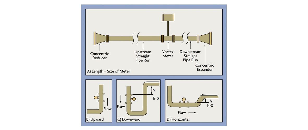
A proper working vortex meter demands that the flow be smooth and even all the way through, without any irregularities. Hence, vertical piping up and down the lake is required to help condition the water¡¯s currents. For proper measurements, the straight pipe length has to match the size of the meter and should equal about 65% of the length of an orifice pipe that uses a beta ratio of 0.7 (Figure 3). Experts urge that the distance downstream of the valve should be greater than 30 times the pipe¡¯s diameter, and that the difference between the meter and the next pressure point should not be greater than 4 times the size of the pipe. Temperature sensors ought to be modest in size and placed 5 to 6 diameters past the subject.
More than fifty percent of vortex meter placements involve decreasing the size of oversized piping with the use of concentric reducers and expanders. Even with straighteners placed, it¡¯s necessary to have some fluid parts still.
Vortex meters can be fitted in any direction as long as they are kept submerged in water. It is possible to keep the meter¡¯s water chamber filled by installing the device at an upward direction in the pipeline (Figure 3-B). While setting up the meter in a downward (Figure 3-C) or horizontal flow (Figure 3-D), make sure the downstream pipes are raised a bit. When the flow stops in the pipes, the pump will bring more liquid in with the help of check valves. Block and bypass valves are needed when it is necessary to stop and then open the process to replace the sensor in a certain design.
The diameter and smooth bore of the flanges at the meter inlet (on schedule 40 or 80 piping) must match those of the meter. It is best to go with weld neck flanges instead of reducing flanges. The mating pipe¡¯s inside should not have any mill scale, pits, holes, reaming scores or bumps at least 4 diameters upstream and 2 diameters downstream of the meter. The bore holes, the gaskets, and the piping close by should all be finely aligned to prevent any obstructions.
Size and Range capacity
When the fluid in the pipe speeds up, the vortex shedding frequency also increases and so does the flow rate. Vortex formation in a flow due to shedding doesn¡¯t depend on the density, viscosity, or conductivity of the fluid, only that the flow has to be turbulent. There is a connection between vortex frequency and the speed of the fluid.
St = f(d/V)
The numerator of Ro is the Strouhal number, multiplied by the vortex shedding frequency, whereas in the denominator, Ro has the bluff body¡¯s width divided by average fluid velocity. Scientists measure the value of the Strouhal number in experiments and discover that it usually remains the same with changes in Reynolds number. Strouhal number means the ratio of one vortex shedding period (l) to bluff body width (d). In Figure 4, this ratio is about six. The Strouhal number serves as a dimensionless variable that describes several kinds of bluff bodies. Should their Strouhal number match, it follows that their behavior and overall results will also be very similar.

Because the volumetric flow rate Q is the product of the average fluid velocity and of the cross-sectional area available for flow (A):Q = AV = (A f d B)/Stwhere B is the blockage factor, defined as the open area left by the bluff body divided by the full-bore area of the pipe. This equation, in turn, can be rewritten as:Q = fKwhere K is the meter coefficient, equal to the product (A f d B). As with turbine and other frequency-producing flow meters, the K factor can be defined as pulses per unit volume (pulses per gallon, pulses per cubic foot, etc.). Therefore, one can determine flow rate by counting the pulses per unit time. Vortex frequencies range from one to thousands of pulses per second, depending upon the flow velocity, the character of the process fluid, and the size of the meter. In gas service, frequencies are about 10 times higher than in liquid applications.
Water calibration in a flow lab is the common approach used by the manufacturer to set the K value. As the K factor is the same for liquids, gases, and vapors, the result from water calibration applies for all other fluids too. When Reynolds numbers are moderate, the calibration factor (K) does not change as a result of edge sharpening or other measurements taken on a square-edged orifice meter. Even though vortex meter equations are easy, there are many points to be aware of. Any manufacturer who offers free computer software for sizing will let you enter the properties of the fluid and will set the correct meter for you in return. Vortex pressure pulse force depends on the density of fluid multiplied by the square of its velocity. Turbulent flow and the minimum force needed to make the sensor function decide what range the meter works with. The signal must have a value that is higher than the fluctuation of noise. As an example, a regular 2-in. vortex meter is designed to measure water flow from 12 to 230 gpm. When the density or viscosity is different from that of water, the meter¡¯s range will not be the same. One should pick a meter that is capable of handling the smallest and highest flows the process will involve. It should be ensured that the minimum flow rate to be measured is at least two times the minimum flow rate that the meter can detect. The maximum flow rate that the meter can handle should be at least five times the predicted maximum flow.
We are a manufacturer of automatic flow meters with many years of experience in the industry. We have strong independent research and development capabilities and are a leader in the flow meter industry. Our main products include electromagnetic flow meters, vortex flow meters, turbine flow meters, ultrasonic flow meters, Coriolis flow meters, various solenoid valves, level meters, control units and valves, etc. Welcome to purchase –Best Instrument