Technical Expert’s Guide: 9 Critical Installation Strategies for Maximizing Electromagnetic Flowmeter Accuracy and Reliability
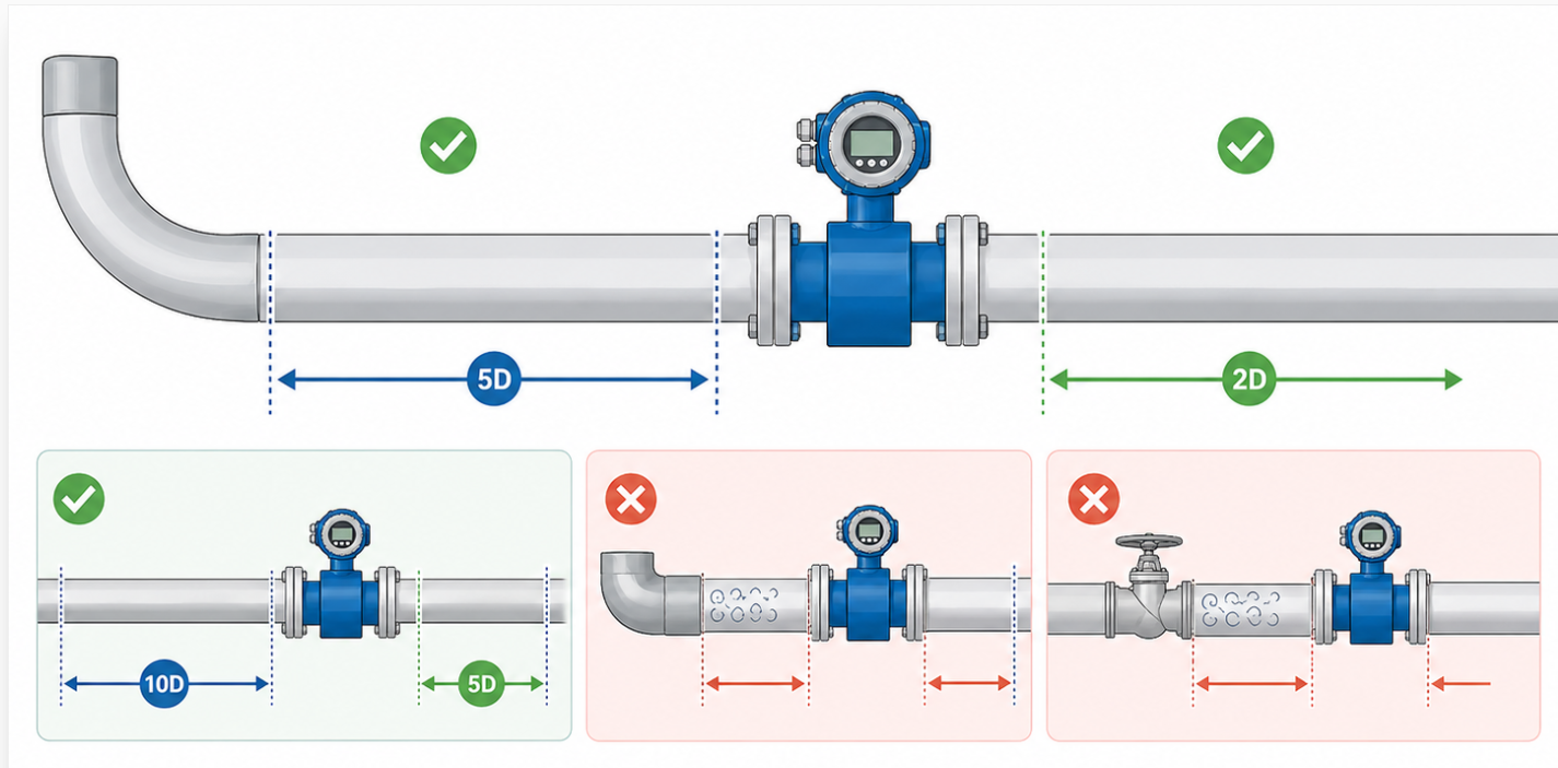
Core Conclusion: You must ensure a minimum of 5D (5 times the nominal diameter) of straight pipe upstream and 2D downstream from the electrode center to eliminate turbulence-induced errors.
Installing an EMF too close to elbows or valves distorts the flow profile, leading to a 2% to 5% measurement deviation. For high-precision requirements, a 10D upstream and 5D downstream configuration is recommended. If the upstream component is a partially open valve or a 90-degree bend in two planes, the upstream requirement increases to 25D to allow the flow profile to stabilize.
1.Upstream: ≥5D (Standard), ≥10D (High Precision).
2.Downstream: ≥2D.
3.Post-Valve: ≥10D from the control valve discharge side.
Core Conclusion: Install the flowmeter at the lowest point of a “U-shaped” pipe section or in a rising vertical pipe to guarantee the measuring tube remains 100% full at all times.
1.Upstream: ≥5D (Standard), ≥10D (High Precision).
2.Downstream: ≥2D.
3.Post-Valve: ≥10D from the control valve discharge side.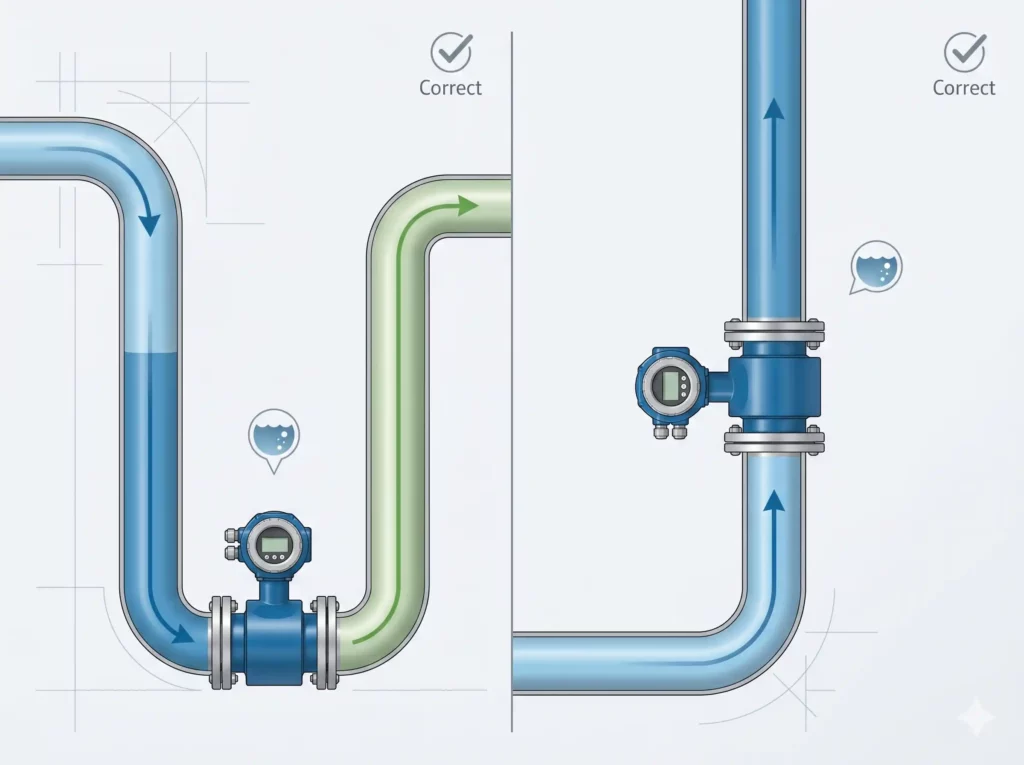
Core Conclusion: A grounding resistance of <10 Ω is mandatory to provide a zero-potential reference point and shield the microvolt-level flow signals from stray currents and VFD noise.
The signal generated by the electrodes is typically in the range of 100 μV to 1 mV. Without a stable ground, external electrical noise from pumps or motors can easily swamp this signal. If the pipeline is plastic or lined with insulating material, you must use grounding rings (316L or HC) to contact the fluid directly and bridge it to the sensor’s grounding terminal.
1.Metal pipes: Connect the sensor ground directly to the pipe flanges.
2.Plastic/Lined pipes: Install grounding rings on both ends of the meter.
3.Target: Resistance to earth must be verified with a ground tester to be <10 Ω.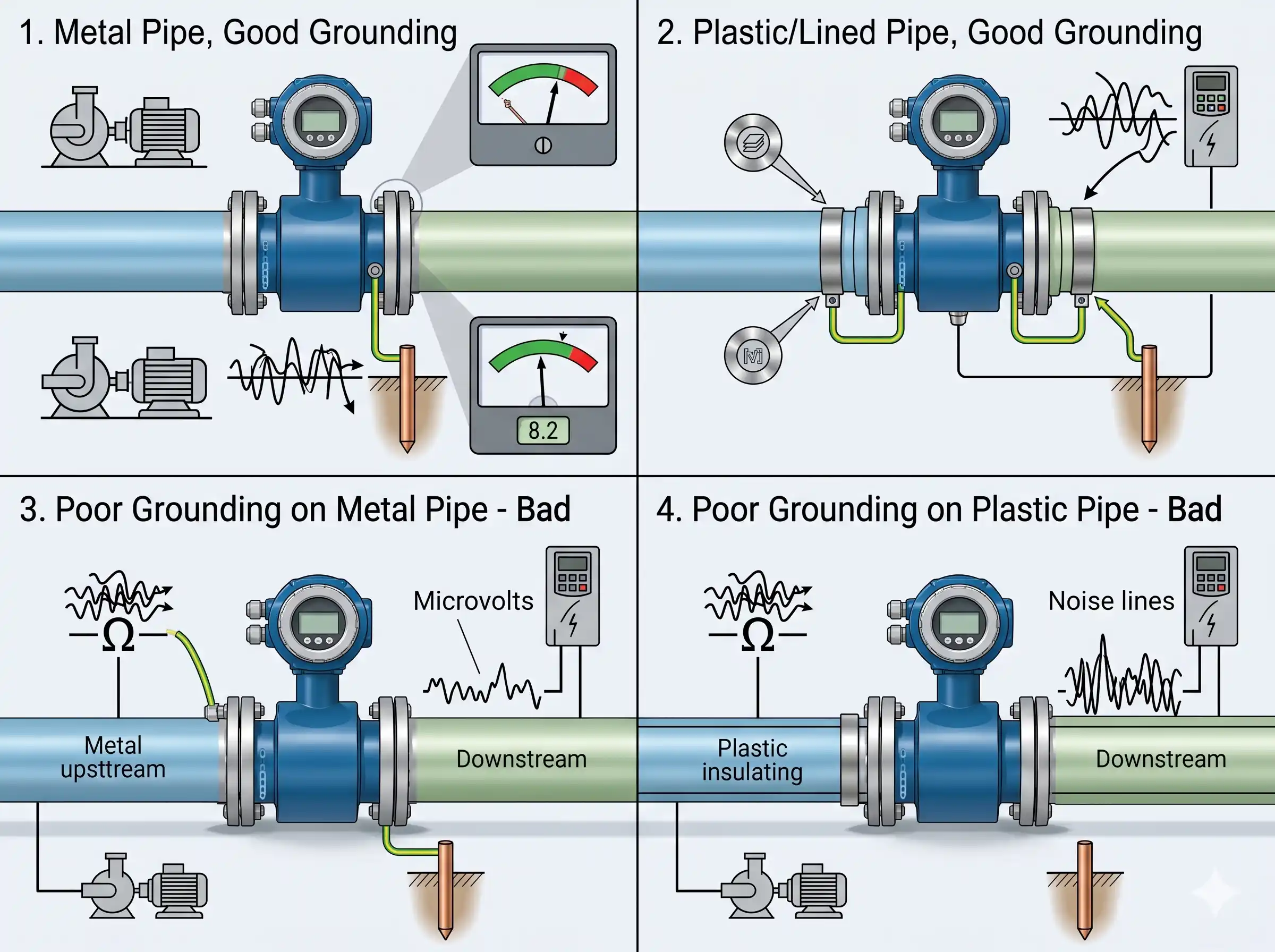
Core Conclusion: The electrode axis must be strictly horizontal (at the 3 o’clock and 9 o’clock positions) to prevent insulation by air bubbles at the top or burial by sediment at the bottom.
If electrodes are oriented vertically (12 and 6 o’clock), air bubbles traveling along the top of the pipe will cause intermittent signal loss, while heavy solids or scale settling at the bottom will short-circuit or insulate the lower electrode. A horizontal orientation ensures the electrodes remain in the “scoured” zone of the flow, maintaining consistent contact with the conductive fluid.
1.Correct: 3 o’clock and 9 o’clock.
2.Incorrect: 12 o’clock (air risk) or 6 o’clock (sediment risk).
3.Tolerance: Ensure the horizontal alignment is within ±10∘ of the true horizon.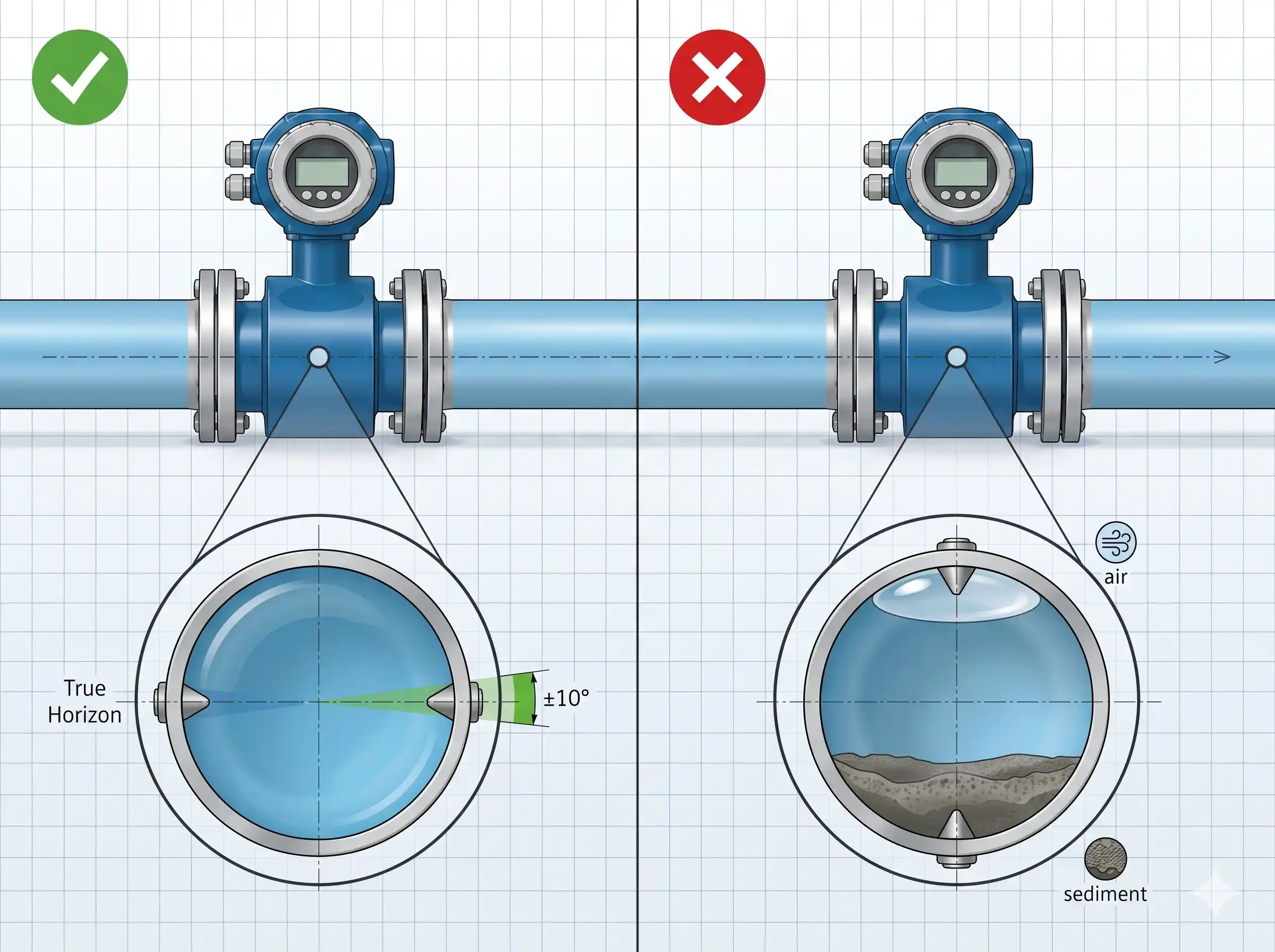
Core Conclusion: Absolutely not; all flange welding and pipe modification must be completed and cooled before the flowmeter is bolted into place to prevent irreversible liner damage.
The internal liners of EMFs (typically PTFE, PFA, or Neoprene) are sensitive to extreme heat. Welding a flange while the meter is attached will melt the liner or damage the internal electrode seals, leading to immediate leaks or vacuum collapse. Furthermore, the high-frequency currents from arc welding can destroy the sensitive electromagnetic coils and converter electronics.
1.Sequence: Weld flanges → Clean pipe → Cool to ambient → Install meter.
2.Protection: Use temporary “spool pieces” during the welding and flushing phase.
3.Risk: Thermal deformation of PTFE occurs above 200∘C.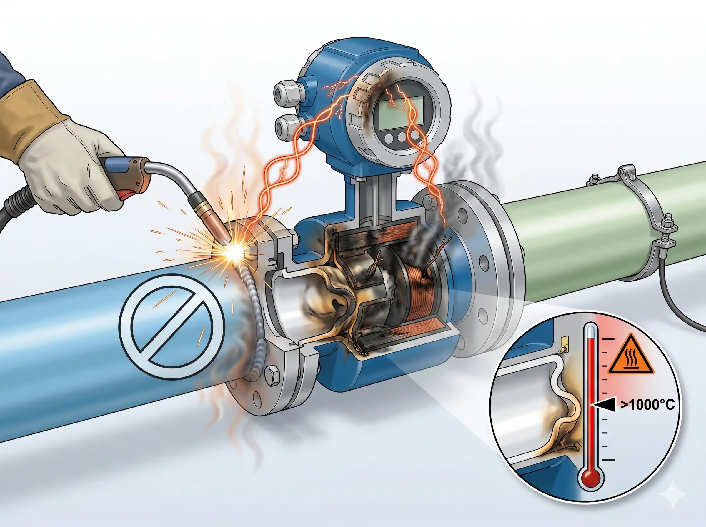
Core Conclusion: For buried or flooded applications, the sensor must be IP68-rated, the junction box must be vacuum-sealed with professional potting resin, and the remote converter must be installed above ground.
An IP67 rating is only for temporary immersion. For long-term burial (IP68), the moisture-proof integrity of the cable entry is the most common failure point. Capillary action can pull water through the cable jacket into the sensor housing over time. We require the use of two-part epoxy potting kits to seal the connection terminals completely before backfilling.
1.Submergence limit: IP68 rated for 3–10 meters depth.
2.Sealing: Use silicone or epoxy resin in the terminal box.
3.Conduit: Use stainless steel or high-density PE conduits for cable protection.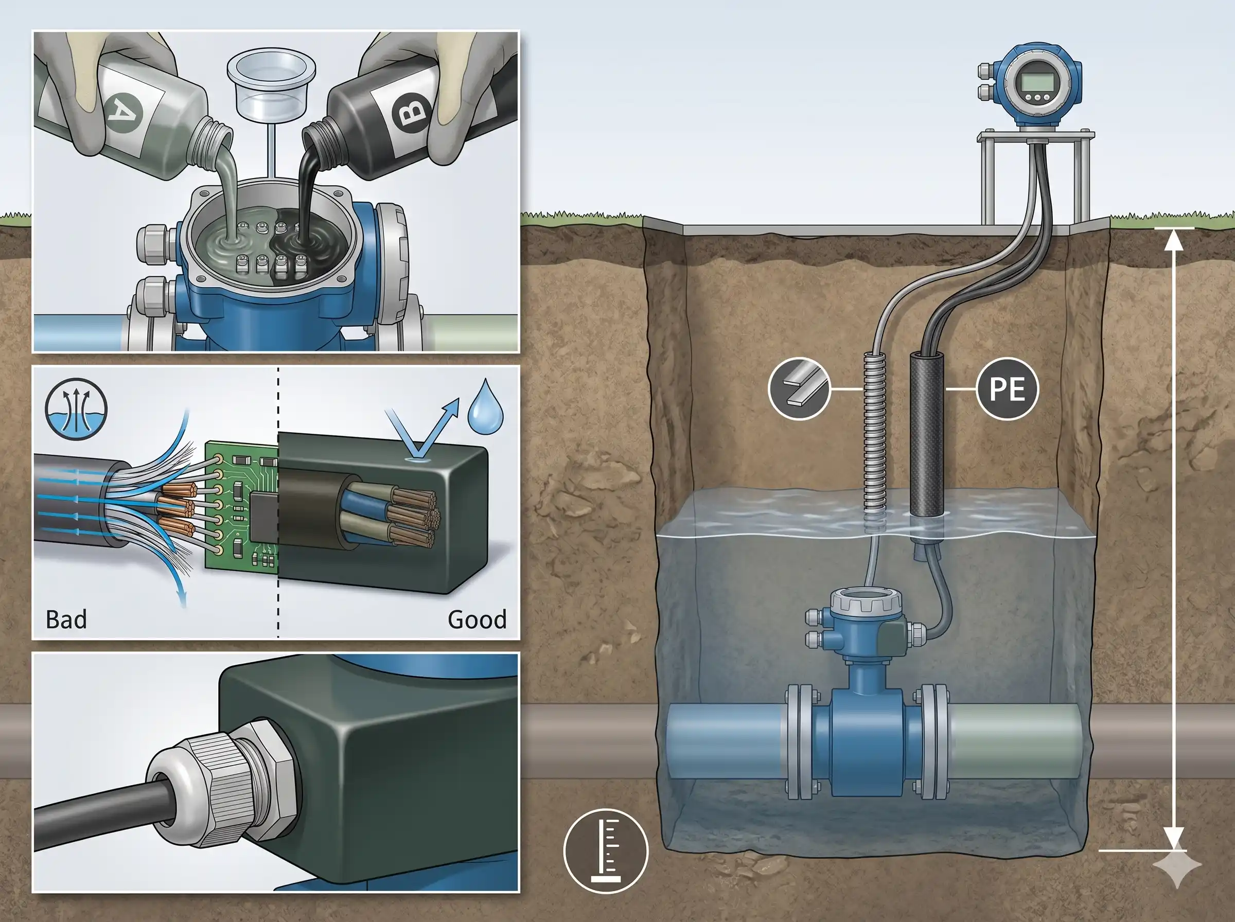
Core Conclusion: If pipe vibration exceeds 2.2 g in the 20–150 Hz range, you must install flexible bellows or support brackets within 1D of the flowmeter flanges.
High-frequency vibration can cause mechanical stress on the electrode seals and introduce “microphonic” noise into the flow signal, appearing as a fluctuating zero point. In workshops with heavy reciprocating pumps, rigid anchoring of the pipe on both sides of the meter is the only way to ensure the 0.5% accuracy spec is met.
1.Vibration limit: Max acceleration <2.2 g.
2.Solution: Install pipe supports/hangers on both the inlet and outlet flanges.
3.Decoupling: Use rubber expansion joints if the vibration is severe (>5 g).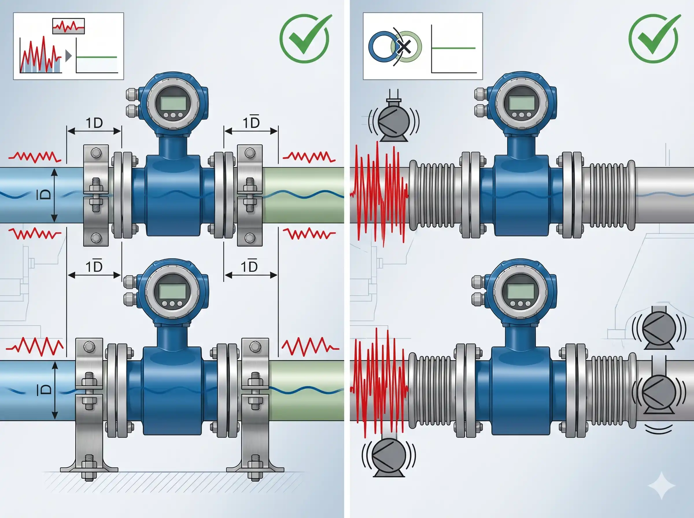
Core Conclusion: Gaskets that protrude into the flow stream create localized turbulence (vortices) that can cause a 1–3% measurement offset even with proper straight pipe runs.
A gasket with a smaller ID than the flowmeter acts as an orifice plate, creating a pressure drop and a non-uniform flow profile across the electrodes. Always select gaskets with an internal diameter 1–2 mm larger than the meter’s bore. Ensure the gasket is perfectly centered; a misaligned gasket is a primary cause of “unexplained” flow instability during commissioning.
1.Gasket ID: Must be ≥ Flowmeter Bore ID.
2.Centering: Use “self-centering” gaskets or flange bolts to ensure alignment.
3.Material: Use soft EPDM or PTFE-envelope gaskets to avoid over-torquing the liner.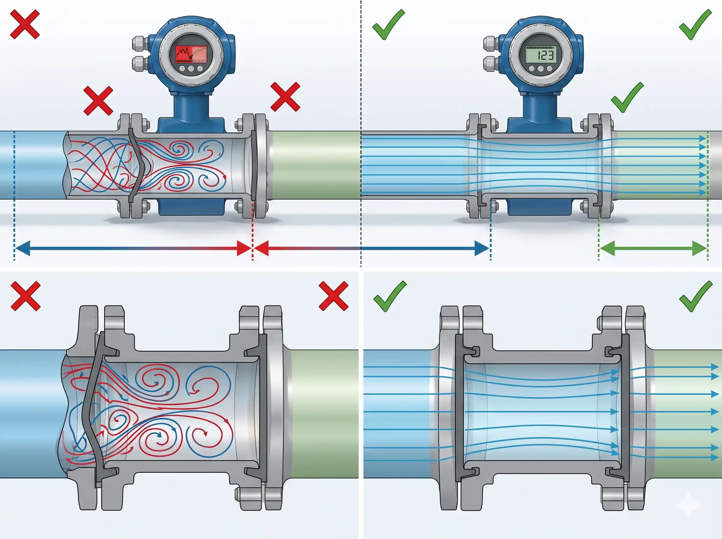
Core Conclusion: VFDs generate high-frequency common-mode noise; you must separate VFD output cables from EMF signal cables by at least 50 cm and use a dedicated high-frequency ground.
VFD interference typically manifests as a “drifting” flow reading that changes whenever the pump speed changes. In addition to the standard <10 Ω ground, the flowmeter converter should be powered through an isolation transformer or a dedicated clean-power circuit if the VFD noise is severe.
1.Separation: Do not run signal and VFD power cables in the same tray.
2.Shielding: Use braided copper shielded cables for the VFD motor output.
3.Filtering: Install an EMI filter on the VFD power input if fluctuations persist.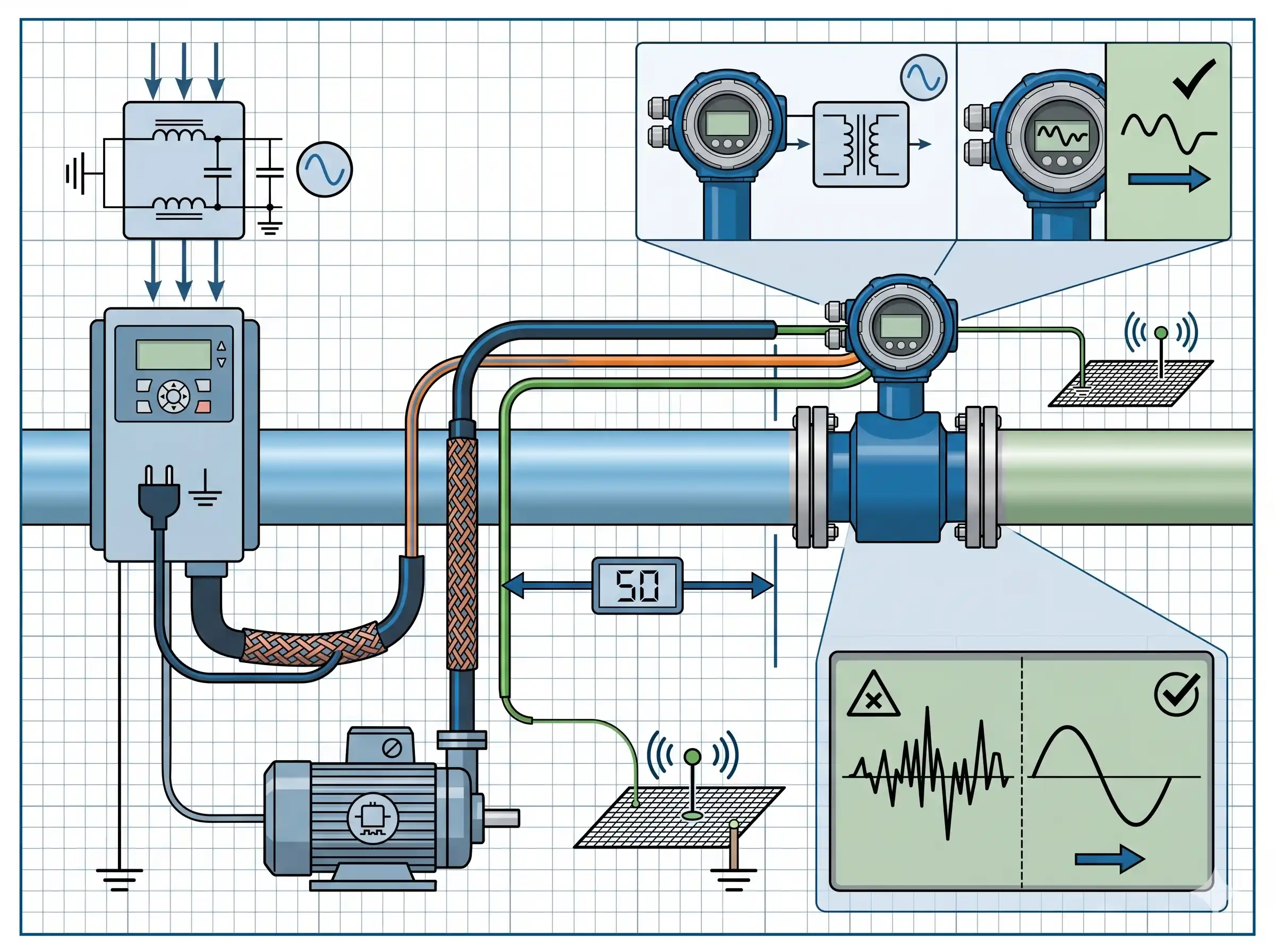
admin
System Administrator
Thank you for reading our technical insights and industry news.