Empty Pipe Alarms in Electromagnetic Flowmetersempty pipe detectionEmpty Pipe Alarms in Electromagnetic Flowmeters
Core Conclusion: To eliminate empty pipe alarms, prioritize a “U-bend” installation at the system’s lowest point, maintain a minimum backpressure of 0.05 MPa, and ensure grounding resistance is strictly < 10 Ω. These technical safeguards ensure electrodes remain submerged and signal impedance stays within the stable 5-20 μS/cm range.
Why “Empty Pipe” Alarms Are More Than Just a Nuisance
In my 15 years of field service, I’ve seen “Empty Pipe Detection” (EPD) triggers cause millions in lost revenue due to unnecessary batch shutdowns. An Electromagnetic Flowmeter requires a 100% full cross-section because the Faraday Law of Induction (E = kBDv) assumes a constant conductor volume. When air pockets interrupt the circuit between the measuring electrode and the reference ground, the signal impedance spikes, forcing the converter to “fail-safe” at zero or maximum flow.
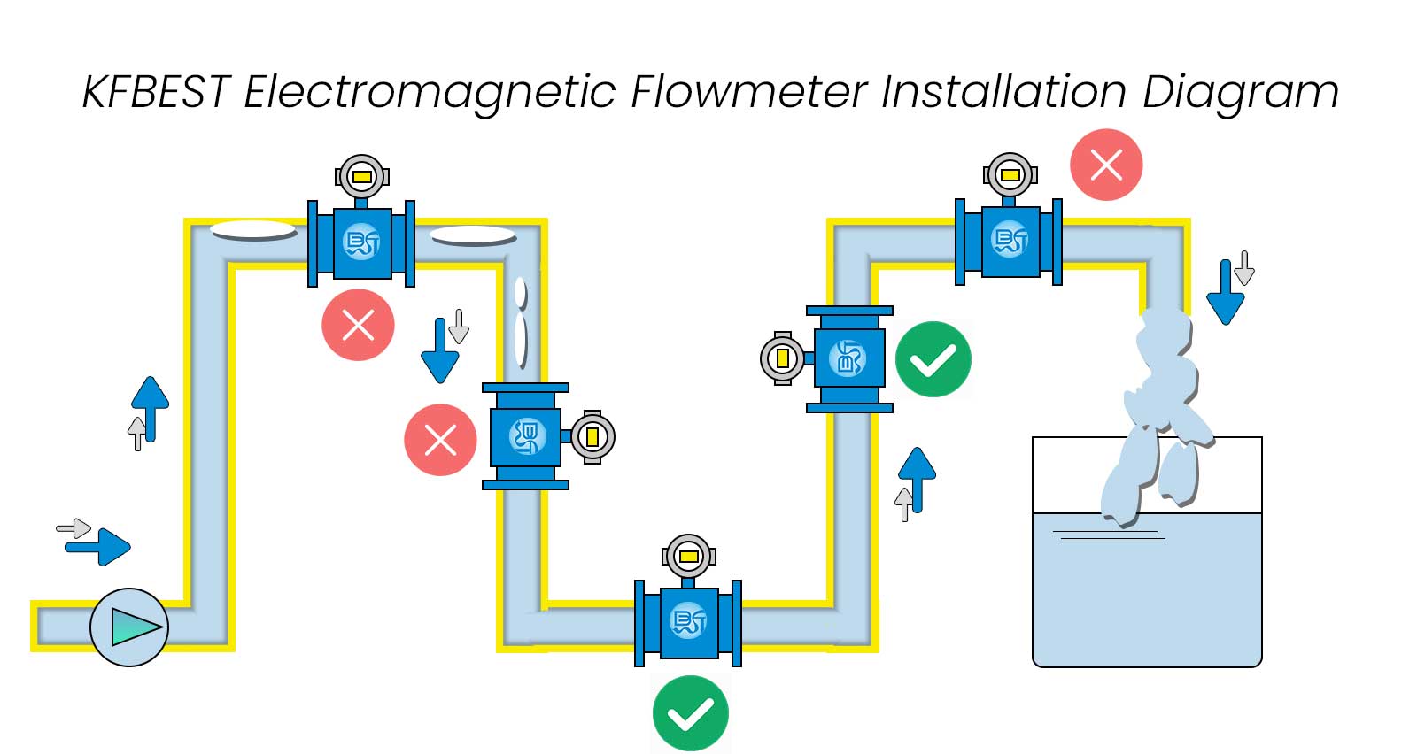
1. Hydraulic Positioning: The “U-Bend” and Vertical Upward Standard
Correct physical placement is the non-negotiable foundation for any Electromagnetic Flowmeter installation. To prevent air from settling on the electrodes, the meter must never be placed at the highest point of a piping run where gas naturally accumulates.
- Vertical Upward Flow: This is the industry gold standard. Flowing from bottom to top ensures that gravity works with the fluid to naturally displace air.
- The U-Section: In horizontal runs, install the Electromagnetic Flowmeter in a depressed “U” section. This creates a natural liquid trap that keeps the sensor submerged even during zero-flow conditions.
- Avoid Discharge Points: Never install a meter at the end of a downward-sloping pipe or just before an open discharge, as siphoning will inevitably create a partial vacuum and trigger the EPD alarm.
2. Maintaining Active Line Pressure (≥ 0.05 MPa)
A common “hidden” cause of empty pipe alarms is insufficient backpressure, particularly in gravity-fed systems. If the fluid velocity is high but the pressure is near atmospheric, gas breakout (cavitation) occurs.
- Backpressure Valves: Install a control or check valve downstream (at least 2D away from the meter) to maintain a positive internal pressure of at least 0.05 to 0.1 MPa.
- Pump Placement: Always install the Electromagnetic Flowmeter on the discharge side of the pump. Installing it on the suction side creates a vacuum that pulls dissolved gases out of the liquid, coating the electrodes in bubbles and triggering false alarms.
3. Precision Grounding: The < 10 Ω Requirement
Many “Empty Pipe” alarms are actually electrical noise alarms caused by poor grounding. If the fluid potential is not identical to the sensor potential, the EPD circuit—which measures electrode impedance—cannot accurately distinguish between fluid and air.
- Grounding Rings: For plastic or lined pipes, stainless steel or Hastelloy grounding rings are mandatory to contact the fluid directly.
- Resistance Standard: Use a ground resistance tester to verify the connection is strictly < 10 Ω. High resistance prevents the converter from accurately sensing the presence of fluid via the electrode-to-ground path.
4. Advanced EPD Parameter Tuning (Impedance & Delay)
Factory default settings for Empty Pipe Detection are often too sensitive for fluids with low conductivity (near 5 μS/cm) or high entrained air, such as milk or pulp.
- Conductivity Threshold: If your fluid is near the 5 μS/cm limit, you must adjust the EPD threshold in the converter menu to prevent “flickering” alarms caused by minor signal fluctuations.
- Alarm Damping: Set a “Confirmation Time” or “Alarm Delay” of 3 to 5 seconds. This allows micro-bubbles to pass through the measuring tube without triggering a full system shutdown, provided the flow signal stabilizes immediately afterward.
5. Managing Electrode Scaling and Coating
Over time, fats, oils, or mineral scales (such as calcium carbonate) can coat the electrodes. This coating acts as an insulator, mimicking an “empty pipe” condition even when the pipe is physically full.
- Electrode Material: In coating-prone applications, specify Bullet-head (self-cleaning) electrodes rather than flat ones. This design encourages the flow to “scour” the surface and prevent buildup.
- Maintenance Schedule: If your process involves slurries or “sticky” fluids, implement a quarterly inspection. A 1 mm layer of non-conductive scale can increase electrode impedance by over 500%, leading to permanent EPD triggers.
Technical Checklist for Commissioning Engineers
| Parameter | Requirement | Why it Matters |
|---|---|---|
| Straight Pipe Run | ≥ 5D Upstream / 2D Downstream | Minimizes turbulence and air bubble entrainment. |
| Line Backpressure | ≥ 0.05 MPa | Prevents siphoning and gas breakout (cavitation). |
| Grounding Resistance | < 10 Ω | Provides a stable zero-potential reference point. |
| Electrode Orientation | Strictly 3 & 9 o’clock | Avoids air at the top and sediment at the bottom. |
| Fluid Conductivity | > 5 μS/cm (Standard) | The minimum threshold for stable impedance sensing. |
Conclusion
Preventing empty pipe alarms in an Electromagnetic Flowmeter is a matter of Hydraulic Integrity and Electrical Precision. By enforcing the 5D/2D piping rule, maintaining positive backpressure, and ensuring a robust ground, you can eliminate 95% of false triggers.
As a technical director, my final advice is always: “Don’t just fix the alarm in the software; fix the fluid state in the pipe.”
admin
System Administrator
Thank you for reading our technical insights and industry news.